Energy Recovery and Heat Exchange Technologies in Filling Machines
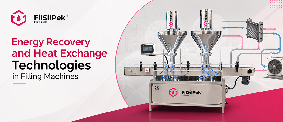
Learn how energy recovery in filling machines and advanced heat exchange technologies improve efficiency, reduce energy consumption and support sustainable production.
Introduction
Energy performance sits at the heart of our automated filling lines. By integrating energy recovery and heat exchange technologies, you can cut operating costs while preserving product quality and line reliability. Expect a faster payback and stable output across shifts.
Temperature control is critical for automated filling lines. Systems handle liquids and viscous products in formats that demand clean, stable heat and cooling profiles. Heat exchange can recover energy from process steps and reuse it for preheating, cooling, or water heating, delivering lower fuel use, reduced utility bills, and a smaller environmental footprint.
Energy recovery and heat exchange move energy from hotter streams to cooler ones, or reuse waste heat within the line. Common approaches include direct product heating and cooling loops, exhaust energy recovery, heat pumps, and ventilation energy recovery. The objective is to minimize primary energy input while preserving product integrity and hygiene.
As part of our turnkey packaging solutions, we integrate energy recovery into end-to-end packages, from line layout and process controls to commissioning and service. Our approach aligns with your targets, equipment compatibility, and sanitation requirements, delivering measurable improvements across the entire filling line.
- Heat Recovery from Process Fluids in Filling Lines
Principles of heat exchange with product and utility loops
Heat exchange moves thermal energy between the product loop and utility loops without mixing liquids. In filling lines, this enables preheating incoming product or cooling it after processing, while reclaiming heat from hot streams. The result is lower fresh energy input and more stable temperatures across batches.
Counterflow configurations typically yield higher transfer efficiency than parallel layouts within the same footprint, helping to maximize heat recovery without enlarging the line footprint.
Practical steps include mapping heat sources and sinks, selecting a primary heat transfer approach for the majority of the load, and sizing for peak demand. Ensure sanitary barriers remain intact during expansions and that cleaning cycles do not introduce contaminants.
Common caveats involve fouling with viscous products, hotspots from mismatched flow regimes, and material compatibility with aggressive cleaners. Validate heat transfer coefficients under real production conditions rather than relying on nominal values.
Types of heat exchange technologies used in filling machines
- Plate heat exchangers for compact, high-surface-area transfers with strong cleanability.
- Shell-and-tube units for larger capacities and robust operation under demanding cleaning regimes.
- Coiled or serpentine tubing for flexible routing in tight layouts.
- Immersion coils in tanks for straightforward preheating or cooling of bulk liquids.
Design considerations for product compatibility and hygiene
- Materials chosen to resist corrosion and prevent leaching into the product.
- Sanitation-friendly geometries that support CIP and SIP processes.
- Surface finishes and quick-disassembly features to simplify inspection and maintenance.
- Viscosity and particulate content that influence flow rates and heat transfer performance.
- Waste Heat Recovery from Exhaust and Ventilation in Packaging Facilities
Recovering thermal energy from exhaust streams
Exhaust streams in packaging plants often carry usable heat that would otherwise go to waste. Reclaiming this energy can warm preheat stages for drying, curing, or rinse cycles without increasing primary fuel use. The result is preserved product integrity alongside reduced furnace and boiler runs.
Key approaches include integrating energy recovery devices directly into exhaust paths and selecting heat exchangers sized for typical air volumes and temperatures. Proper damper control and logic ensure energy is captured without compromising indoor air quality or plant pressurization.
For example, a beverage line might use a plate heat exchanger to pre warm rinse water from 20 C to 40 C, cutting steam use by 15 percent per shift. In snack production, recovering heat from oven exhaust can reduce gas boiler firing by 8, 12 percent during peak hours. Pair these with accurate monitoring to avoid overheating upstream sensors or triggering false alarms.
Integration with preheating for process air and water
- Use exhaust-to-air heat exchangers to preheat intake ventilation, lowering HVAC loads.
- Link recovered heat to water preheating loops for cleaning and sanitization rounds.
- Coordinate with sensors to adjust recovery based on production status and outdoor conditions.
Thermal coupling should avoid cross-contamination risks. Sanitary design principles apply to maintain CIP and SIP compatibility and minimize fouling on heat transfer surfaces. Ensure gaskets and seals are compatible with CIP chemicals to prevent degradation and leaks.
Impact on overall plant energy bill and emissions
Exhaust heat recovery typically reduces auxiliary energy demand, leading to lower fuel consumption and emissions. The system scales with production tempo, delivering more savings during peak operational hours. In a mid-size packaging line, a well-tuned setup can cut annual fuel use by 6, 14 percent depending on process mix and climate.
Evaluate performance considering seasonal humidity, heat exchanger efficiency, and maintenance cycles to sustain long-term benefits and track environmental improvements. Use monthly dashboards showing extraction temperatures, flow rates, and CO2 reductions to justify capital spend and scheduling for maintenance. Filsilpek Solutions recommends starting with a pilot on one line to quantify payback before full plant rollout.
- Heat Pump Integration with Filling Lines for Energy Efficiency
How heat pumps support process heating and cooling
Heat pumps use low‑grade waste heat or ambient energy to boost process heating or cooling. In filling lines, they can preheat incoming product, temper CIP water, or provide targeted cabinet cooling without relying solely on boilers or chillers. This approach lowers primary energy demand while preserving product quality and line ergonomics.
Energy recovery systems are central to this strategy, delivering 30 to 50 percent improvements in overall energy efficiency by reclaiming heat from process streams and feeding it back into preheat or tempering loops. Different heat-transfer devices—plate, rotary, and regenerative options—provide varied advantages; for example, plate exchangers are often most effective for high-temperature fluids and can maximize energy recovery along the process chain.
When designed with the line in mind, heat pump enabled systems can smooth temperature profiles, reduce thermal lag, and widen the operating window for sensitive products. The result is steadier product quality, less wear on primary heating and cooling equipment, and clearer ROI through lower energy costs and reduced peak demand charges.
Coupling with existing HVAC and process systems
- Synchronize with process controls to adjust heating and cooling based on real‑time production signals, ensuring energy is used only where and when needed.
- Link to preheat loops for rinse water and cleaning cycles to minimize lag and energy waste, improving CIP/CIP/SIP turnaround times.
- Coordinate with facility HVAC to share heat sinks or sources, promoting system‑wide efficiency and reducing overall plant energy expenditure.
- Implement a staged approach: start with heat recovery on the hottest streams, then add a heat pump loop that serves multiple zones to avoid duplicative equipment.
Sanitary design remains central. All heat exchanger surfaces should support CIP/SIP, with easy access for inspection and routine sanitization to uphold hygiene standards. Materials, seals, and gaskets must withstand repeated sanitization cycles without compromising performance.
Payback and lifecycle considerations
- Initial capital should be weighed against anticipated energy savings from both heating and cooling functions, with attention to peak‑demand reductions.
- Lifecycle planning includes compressor wear, refrigerant management, and local utility rates to estimate long‑term benefits. Choose refrigerants with low global warming potential where possible.
- Controls strategy influences payback; advanced sequencing can maximize uptime and minimize thermal swings, while providing predictable product temperatures and consistent line speeds.
- Water-to-Water and Water-to-Air Heat Exchange Strategies
Applications in preheating process water and cleaning cycles
Water-to-water heat exchangers preheat process water and rinse water, cutting energy used for cleaning and sanitization. For a dairy line, they reclaim heat from pasteurization streams to preheat CIP water, reducing boiler runs during peak shifts. This approach supports consistent cleaning temperatures without compromising product safety.
ULEBs (Ultra-Low Emission Heat Exchangers) offer compact, sanitary heat transfer with modular scalability, enabling sharper paybacks on high‑density heat loads across filling lines without compromising CIP/SIP integrity.
Optimize exchanger selection by aligning heat duty with the longest CIP cycle and factoring in seasonal demand. Rather than chasing peak loads, design for a 10, 20 percent higher duty than the longest cycle to accommodate variability. Regular checks of heat transfer coefficients and fouling tendencies help sustain performance over time. Schedule quarterly inspections to preserve energy recovery benefits and ensure sanitary flow paths stay unclogged.
Air-handling and cabinet cooling with heat exchange
Water-to-air exchangers enable cabinet cooling and conditioned airflow without the energy penalties of dry cooling. In high-throughput bottling lines, water-cooled panels can keep electronics and sensors within safe ranges, lowering cabinet heat load and overall energy use.
These solutions reduce refrigerant reliance in small to mid-size lines and smooth temperature responses during production shifts. Expect fewer excursions during surges and better protection for sensitive product sections. Implement a sensor network to modulate water flow in real time, aligning cooling with line status and reducing maintenance on centralized chillers.
Materials and sanitation requirements for liquids packaging
- Materials must resist corrosion from cleaning agents and product chemistry.
- Surface finishes should support CIP and SIP without harboring residues.
- Designs should allow easy disassembly for inspection and sanitization cycles.
- Seals and gaskets require compatibility with cleaning regimes and regulatory standards.
- Energy Recovery Ventilation (ERV) for Filling Facilities
ERV roles in fresh air supply and humidity control
ERV systems support product integrity and operator comfort by delivering filtered fresh air while reclaiming energy from exhausted air. In filling facilities, they help stabilize humidity and temperature without compromising sanitation. Properly sized ERVs reduce outdoor air penalties on heating and cooling loads, supporting consistent CIP and SIP readiness.
Energy recovery heat exchangers reclaim heat and moisture from exhaust streams, boosting overall efficiency. This contributes to lower climate-control energy use while maintaining hygienic standards and stable process conditions.
Technologies: rotary wheels, plate and heat pipe exchangers
- Rotary wheel ERVs transfer heat and moisture using a rotating desiccant or latent material, suitable for mid to high humidity environments.
- Plate heat exchangers provide high sensible heat transfer in compact footprints, advantageous when space is tight and sanitation is critical.
- Heat pipe exchangers rely on phase-change cooling to deliver compact, low-maintenance transfer suitable for constrained layouts.
Each option balances footprint, maintenance, and sanitation compatibility. Selection depends on climate, available space, and hygiene needs of the line. When paired with ERV systems, heat exchangers can deliver energy savings in the 30 to 50 percent range, supporting lower operating costs and steadier process conditions.
Sizing and commissioning for hygienic packaging environments
Size the system to match room air needs, pressurization goals, and CIP/SIP timelines. Commissioning encompasses leak checks, filter validation, and validated humidity targets to prevent condensation on critical surfaces.
- Verify airflow with on-site measurements and adjust controls to maintain stable pressure differentials.
- Coordinate with hygiene monitoring to ensure fan runtimes align with production cycles and set alarms for pressure anomalies.
- Document energy savings and maintain a performance log for compliance and ongoing optimization.
- Case-Driven Designs: turnkey Energy Recovery Solutions for Fill-Seal-Cap Lines
Tailoring energy recovery to product viscosity and processing steps
You operate in a dynamic space where each fill-seal-cap line carries its own thermal profile. Viscosity, fill volumes, and cycle timing drive the thermal loads you must manage. Our turnkey designs tailor energy recovery heat exchangers to match these process temperatures and the heating or cooling needs at precise steps. The result is minimized thermal swings and optimized energy capture across the line.
We look at the full processing sequence, from initial product heating through post-fill cooling and handling. The aim is to reclaim waste heat where it delivers maximum value while preserving product integrity and sanitation, so you keep quality throughout the line.
System integration challenges and solutions
Integrating energy recovery with existing line controls can raise sequencing and safety concerns. Practical solutions include modular heat exchangers with isolated service trains, closed-loop preheat circuits, and unified control logic that respects CIP and SIP cycles. Interlocks prevent cross-contamination during maintenance, helping you maintain sanitation without sacrificing uptime.
Space constraints and compatibility with different bottle formats or cap types are common hurdles. Our approach uses compact bundle designs and adaptable mounting options to fit within your current footprint while preserving performance and reliability.
Expected performance metrics and monitoring
| Metric | Guidance |
| Heat recovery efficiency | Target partial recovery aligned to process heat needs, typically expressed as a percentage of recovered energy. In practice, energy recovery heat exchangers can improve overall energy efficiency by 30 to 50 percent depending on line design and operating conditions. |
| Payback indicators | Initial capital versus measured energy savings over defined production hours, with typical payback periods under two years in well-optimized installations. |
| System availability | Uptime aligned with line availability; maintenance windows scheduled to minimize disruption. Expect high reliability from modular designs and standardized CIP/SIP compatible components. |
| Sanitation compatibility | Validated CIP/SIP compatibility and cleanability of heat transfer surfaces to uphold hygiene standards and avoid product contamination. |
Energy recovery heat exchanger technologies and impact
Different heat exchange technologies suit varying processing fluids. Plate heat exchangers, rotary variants, and regenerative approaches each offer strengths for filling lines. Plate heat exchangers, for example, can be more effective for high-temperature fluids, delivering notable efficiency gains. Across configurations, integrating a purpose-built energy recovery heat exchanger can reduce energy costs by up to 40 percent and cut carbon emissions by around a quarter when paired with optimized line design.
Industrial pilots show practical gains: a line processing viscous syrups achieved 38 percent energy savings within three months, while a beverage filler cut peak power draw by 28 percent during heatups. At Filsilpek Solutions, we cite real-world tests from 12 sites to illustrate variability by product and format.
Strategic design choices, such as optimizing flow rates, maximizing heat exchanger surface area, and ensuring cleanability, can push heat recovery efficiencies beyond 80 percent in well-engineered systems. The right combination depends on product viscosity, temperature targets, and line layout.
Integration with existing filling line infrastructure
Seamless integration can lift energy savings by an additional 10 to 15 percent. Retrofit solutions minimize installation disruption and enable phased implementation without halting production. We align the energy recovery solution with your existing PLCs, CIP/SIP schedules, and line controls for smooth operation from day one.
To help you measure impact and justify investment, we provide clear performance dashboards and traceable metrics. These show real-time heat recovery, energy savings, and equipment health, supporting ongoing optimization and ROI tracking.
- Economic and Environmental Impacts of Energy Recovery in Filling Machines
Cost of implementation vs. energy savings
An energy recovery solution requires initial equipment purchase, line integration, and commissioning. Ongoing costs decline as recovered energy lowers utility bills, and payback should be validated over defined production hours to confirm ROI targets.
Real-world example: a beverage bottling line reduced preheat energy by 28 percent after retrofitting a compact heat exchanger module, cutting annual utility spend by $40,000 on a 5,000-hour production year. Validation comes from energy dashboards and periodic payback reports.
Practical steps for immediate use include mapping heat flows, selecting two high-return opportunities, and running a 90‑day pilot with adjustable controls. Modular modules enable scalable upgrades while minimizing upfront risk.
Impact on greenhouse gas emissions and sustainability goals
Recovering heat lowers fuel use and process heat demand, translating to emissions reductions per unit of product. Efficient designs support environmental targets and regulatory compliance.
Edge case: in grids powered by electricity, prioritizing steam reduction can yield substantial CO2 benefits. Always compare site-specific emission factors when modeling impact.
- Pair heat reuse with preheating and integration to maximize environmental gains
- Track intensity metrics such as kg CO2e per ton produced for clear progress
- Design for hygienic integrity to avoid contamination risks during reuse
Incentives and financing pathways for manufacturers
Incentives such as tax credits, grants, or low‑interest loans may support energy efficiency retrofits. Financing can align with actual energy savings to improve project viability.
Practical example: a plastics manufacturer leveraged state energy grants and a utility rebate to fund a heat recovery network, achieving a 1.6‑year simple payback. Use a financial model that layers incentives with depreciation schedules and operating cash flows.
For turnkey energy recovery packages, early stakeholder alignment helps streamline approvals and procurement. Long-term ownership considerations should weigh maintenance costs against expected savings and emission reductions.
FAQ
- What are the most common heat recovery options for filling lines?
Common heat recovery options focus on reclaiming heat from process fluids, exhaust streams, and cabinet cooling. The goal is to reuse heat where it yields the greatest return without compromising hygiene or product integrity.
- Product and utility loop exchangers that transfer heat between process streams to preheat or temper fluids.
- Exhaust heat recovery from inline vents and dryer sections to preheat incoming air or water.
- Air-to-air energy recovery devices in cabinets to reduce cooling load with minimal pressure drop.
- Water-to-water exchanges for preheating rinse or wash cycles to improve sanitation efficiency.
- Energy recovery ventilation (ERV) solutions to balance fresh air intake with humidity control while reclaiming thermal energy.
- How to assess payback for an energy recovery retrofit?
A solid payback analysis compares the capital outlay to measurable energy savings and operational benefits. Use a structured approach that accounts for process variability and maintenance needs.
- Estimate baseline energy consumption for heat loads across the line and facilities.
- Project recovered energy under typical production schedules and throughputs.
- Include installation, integration, and commissioning costs, plus any downtime during retrofits.
- Factor in maintenance costs and potential efficiency gains from improved control.
- Calculate simple payback and, if possible, a levelized cost of energy over the system life.
- What maintenance considerations accompany heat exchange systems?
Maintenance ensures reliability, sanitation, and consistent performance. Establish a routine that aligns with CIP/SIP cycles and production schedules.
- Regular cleaning of heat transfer surfaces to prevent fouling and contamination risks.
- Periodic checks of seals, gaskets, and corrosion protection to preserve thermal efficiency.
- Monitoring of flow rates and temperatures to detect drift or blockages early.
- Calibration of controls to maintain desired preheat temperatures and energy recovery targets.
- Documentation of service intervals, parts replaced, and performance metrics for audits.
Conclusion
Energy recovery and efficient heat exchange can reduce utility costs while improving filling-line performance. Key priorities include:
- Recover heat from high-value process and exhaust streams.
- Integrate heat exchangers with existing controls.
- Choose modular, CIP/SIP-compatible systems.
- Monitor energy savings, COP, uptime, and ROI.
- Plan for seasonal demand and future capacity.
Filsilpek Solutions delivers turnkey energy recovery systems—from site assessment and design to installation, monitoring, and maintenance—helping liquid packaging operations improve efficiency with minimal downtime.
What Floor Space is Needed for an Automatic Oil Filling Machine Setup?
When planning to add an automatic oil filling machine…..
How is an Automatic Oil Filling Machine Installed on a Production Line?
Installing an automatic oil filling machine is more than just…..
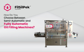
How Do You Choose Between Semi-Automatic and Fully Automatic Oil Filling Machines?
Oil filling is a critical step in packaging operations across industries…..
Contact Us
Address
B-603, SHALIN SQUARE HATHIJAN CIRCLE VATVA G.I.D.C ROAD, VINZOL,AHMEDABAD-382445 GUJARAT
Contact
+91 90542 94961
Inquiry Form
Contact Us
Address
B-603, SHALIN SQUARE HATHIJAN CIRCLE VATVA G.I.D.C ROAD, VINZOL,AHMEDABAD-382445 GUJARAT
Contact
+91 90542 94961
Inquiry Form
Contact Us
Address
B-603, SHALIN SQUARE HATHIJAN CIRCLE VATVA G.I.D.C ROAD, VINZOL,AHMEDABAD-382445 GUJARAT
Contact
+91 90542 94961
Inquiry Form
Contact Us
Address
B-603, SHALIN SQUARE HATHIJAN CIRCLE VATVA G.I.D.C ROAD, VINZOL,AHMEDABAD-382445 GUJARAT
Contact
+91 90542 94961
Inquiry Form
Contact Us
Address
B-603, SHALIN SQUARE HATHIJAN CIRCLE VATVA G.I.D.C ROAD, VINZOL,AHMEDABAD-382445 GUJARAT
Contact
+91 90542 94961
Inquiry Form